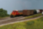
The GNRR North Local works Elizabeth Yard on the new staging cassette.
With the construction of the staging cassette benchwork completed, and the track work installed, it was time to move on to the next phase of construction, electrical. While many model railroaders don’t enjoy installing the electrical components and wiring to make our trains run, it is necessary if we want to see our trains operate. The wiring for our trains has become easier with the advent of DCC, gone are the days of complex block wiring that was necessary with DC if you wanted to run more than one train. This blog is not a tutorial on how to wire your layout, just a few helpful tips and techniques that I use when wiring my layout.
The first step of wiring my staging cassette was installing track feeders. I like to use 22 AWG stranded wires for my feeders as the wire is flexible and easy to install. I start by determining the location of the feeders, about every 3 feet along each piece of track. Next, I needed to drill a hole for the wire next to the rail and between two ties. A problem arose that the longest drill bit I had was too short to drill through the cork roadbed, the 2” of foam, and the plywood base. While longer drill bits are available, they can be difficult to find in a small diameter at your local hardware store. I hit upon a simple solution, a 7” long piece of 3/32” diameter solid steel wire I had on hand was sharpened into a point on one end and chucked into my Dremel tool. It easily drilled through all three layers and the best part was that it did not damage the rail like the drill bits can because it had a smooth shaft. I now have a new “tool” for installing wires on any future layout wiring projects.

I like to keep the 22 gauge feeders to no longer than 6” to reduce the voltage drop. Once I cut the feeder wires to length, I applied flux and tinned the wire. I also cleaned the rail and applied flux and solder. Next, I inserted the wire through the hole next to the rail and then bent a small 45 degree angle to the tinned portion of the wire. I prefer to solder only the very tip of the feeder wire to the rail so that it does not show as much in photos, as opposed to soldering it horizontally along the rail. A quick touch of the soldering iron to the joint and the feeder was soldered to the rail. Any extra solder can be smoothed out with a file so that the wire connection is almost invisible once it is painted.

My main electrical bus wire is 14 AWG stranded wire. The staging cassette DCC wiring is connected to the rest of the layout by using a Cinch-Jones plug. I installed the main bus wire and then connected the feeder wires to it in a couple of different ways. For the bus wire connection in the middle of the run I used suitcase connectors to connect a short secondary 14 AWG feeder wire to the main bus, and then used wire nuts to connect the 22 AWG feeder wires to the secondary feeder. This method limits the number of suitcase connectors needed and allows for both wires in the “standard” 14-18 gauge suitcase connector to be the same size, which are more common and easier to find.

My second method of connecting the feeder wires to the bus was to use a Euro terminal strip connector. These can be found at many home improvement stores in various lengths and can be cut to the number of connectors you need. The wires are inserted into the connector and a screw is tighten to hold them securely in place. This type of connection worked well for the feeders at the beginning and end of the main wire bus run.

With the wiring done, I painted the rails and began ballasting the track once it was dry. I prefer to use Arizona Rock and Mineral (ARM) products as they are made from real stone. I used their HO scale CSX, SP, Wabash (#138-2) and N scale (#138-1) ballast, mixed two parts HO scale ballast to one part N scale for the main line. One the sidings I used only the N scale as I like to allow some the ballast to cover the ties. I also added dropped lading from marble chip hopper cars and small amounts of black weathering powder to simulate dripping oil and grease between the rails. For the areas between the sidings and main line tracks I used the ARM Industrial Dirt (#2000). The gravel road was made using ARMs Driveway and Road Gravel (#135-0). The driveway gravel can be a little hard to find on their website, but you can find it under the 135 Union Pacific Gray Blend and select 0 for the driveway and road gravel product.

With the ballasting done, I decided to go the extra step and add rail joint bars. I planned to use the staging cassette for outdoor photo shoots and I thought the addition of the joint bars would look nice and be a prototypical detail not often modeled. I purchased the Details West RB-933 joint bars from an online seller. The joint bars are made of ABS plastic and this set is designed for code 70 rail. I removed the joint bars from the sprue and glued them every 39’ on the outsides of the rail using CA glue. This was a very tedious process, but it went well once I got the hang of it. Once they were installed I went back and painted them with the rail color. The joint bars don’t stand out when normally viewing the layout, but are noticeable in photos if you really look at the track.
In my next blog I’ll discuss scenery and a few extra details to wrap up this project. Until next time, stay safe and keep model railroading.